White paper
UPS redundancy for Canadian data centres: N+1, 2N, and distributed-redundant architectures compared
An engineering decision framework for module and system redundancy, concurrent maintainability, bypass behaviour and Tier objectives, across manufacturers

A one-line diagram labelled 2N or N+1 states a design intent, not a proven result. Redundancy is a capacity, path and maintenance outcome that has to hold in every required operating, failure and service state, so the label on the drawing is only the starting point. This paper compares the redundancy architectures used in Canadian critical facilities, sets out what each one does and does not prove, and gives a state-based method for testing a topology against concurrent maintainability (servicing any component without dropping the IT load), static and maintenance bypass behaviour, single points of failure and Uptime Institute Tier objectives.
This white paper is an evidence-led engineering comparison that implies no endorsement, and every performance or availability figure is attributed to the source that publishes it.
The intended readers are Canadian data-centre facility managers, electrical engineers, consultants and critical-power procurement leads who must set a redundancy target and then prove it through design, commissioning and maintenance. The treatment covers every major manufacturer. Product families from Eaton and Schneider Electric appear only as examples of a topology or a documented bypass behaviour, because their published manuals and procedures are the sources cited here, and never as a recommendation. A reader who needs only the summary can go directly to the topology comparison matrix and the decision checklist below.
The redundancy decision this paper addresses
The recurring decision on a three-phase critical-power project is not which brand to buy. It is how much redundancy the facility actually needs, at which layers, and how the choice will be proven when a component fails or is taken out for service. Higher resilience raises capital cost, idle losses and control complexity, so the target should follow the facility's real availability requirement rather than a default topology.
The difficulty is that one label can describe very different installed systems. Two frames on a shared bus, four systems on two independent paths, and three systems shared across two load blocks can each be called redundant, yet they fail, transfer and maintain in different ways. A useful comparison therefore has to separate capacity redundancy from path independence, and both of those from concurrent maintainability. The sections below define each architecture by what it must prove, compare the options on the criteria that change a decision, and end with a checklist a Canadian owner can apply before committing to a target.
Terms, system boundary and assumptions
N is the capacity required to support a defined critical load in a named operating state. The definition records the included loads, the coincident demand, the peak and its duration, phase imbalance, power factor, temperature and altitude derating, the required cooling and controls, committed growth and the maintenance state. N is not automatically the UPS nameplate, the future maximum, the average load, the sum of connected nameplates, one module or one frame.
The system boundary for this comparison runs from the utility and generator sources, through switchgear, the UPS and its bypass paths, the batteries and DC system, to the downstream power distribution unit (PDU), remote power panel (RPP), busway, static transfer switch (STS) and rack power feeds. It also includes the non-electrical dependencies that can defeat a redundancy claim: cooling equipment and its controls, fuel supply, emergency power off (EPO) and fire interfaces, and the programmable controllers, communications and firmware that coordinate the plant.
Two assumptions apply throughout. First, the dominant topology for loads above roughly 20 to 30 kW is online double conversion, which rectifies incoming alternating current to a direct-current bus and re-inverts it to a regulated output, so the battery, static bypass and paralleling all tie to that bus. Second, redundancy is evaluated as a per-facility engineering decision expressed as N, N+1, 2N or distributed-redundant, not as a fixed property of a product. Battery sizing under IEEE 485 (the standard for sizing stationary lead-acid battery banks), protection coordination and detailed cooling design are named where they affect a redundancy conclusion, but their full treatment sits outside this comparison.
How redundancy is proven: N defined by state, not by nameplate
N+1 exists only when removing the defined largest required capacity component leaves qualified components able to supply N. The design must state which component qualifies as the one that can be lost: one power module, one UPS frame, one generator, one battery string or one cooling unit. An N+1 module count on its own does not prove a second power path, fault tolerance, an independent battery, a redundant bypass or independent distribution.
Because the count follows from the load basis, the load basis has to be measured before the count is fixed.
What does N+1 look like with 250 kW modules?
Consider an illustrative critical load of 800 kW served by 250 kW power modules. Three modules give 750 kW, which is below the load, so N requires four modules at 1,000 kW of installed capacity. An N+1 line-up installs five modules; after one module is lost, the remaining four still deliver 1,000 kW against an 800 kW load, a reserve of 200 kW, or 25 percent of the load.
That 25 percent reserve follows from the 800 kW to 250 kW load-to-module ratio in this illustration and is not a general property of N+1; a load equal to an exact multiple of the module rating would leave no reserve after the spare is lost.
The same five-module line-up also fails to hold N if the true measured load turns out to exceed 1,000 kW, which is why N has to be defined on measured load plus documented growth rather than a nominal request. These figures are an illustrative capacity arithmetic, not a site measurement, and the arithmetic alone does not prove independent distribution, battery autonomy, bypass capacity, cooling or controls.
2N means two systems or paths, each individually capable of N in the required condition. The proof examines the utility and generator source, the switchgear and bus, the UPS and bypass, the batteries, physical separation, controls, cooling, the PDU, RPP, busway and rack distribution, and both dual-cord and single-cord loads. A common generator control, EPO relay, cooling zone, downstream panel, or both load cords landing on one source can defeat the claim even when the diagram shows two of everything.
Module redundancy versus system redundancy
Module redundancy lives inside a frame. A modular or scalable UPS uses hot-swappable power modules that share a common frame, static bypass and controls, so capacity grows by adding modules and one installed spare yields an intrinsic N+1 at the module layer. The Eaton 93PM and the Schneider Galaxy VS, VL and VX families follow this pattern. The trade-off is that the shared frame, the shared bus, the shared static bypass and the shared controls can each become a common element unless the design isolates them, and a single frame concentrates a large block of capacity.
System redundancy lives between frames or between complete trains. A parallel or redundant configuration ties two or more frames onto a shared paralleling bus and sizes the group so the survivors carry the full load when one frame is removed, which is N+1 at the frame level. A 2N arrangement goes further and provides two complete independent systems, each able to carry the whole load on separate paths from source to load. The engineering point is that module redundancy protects against a module fault inside one frame, while system redundancy protects against the loss of a whole frame or path. A design can hold N+1 at the module layer and still have a single downstream bus or breaker as a common point of failure, so the layer at which redundancy is claimed must be stated explicitly.
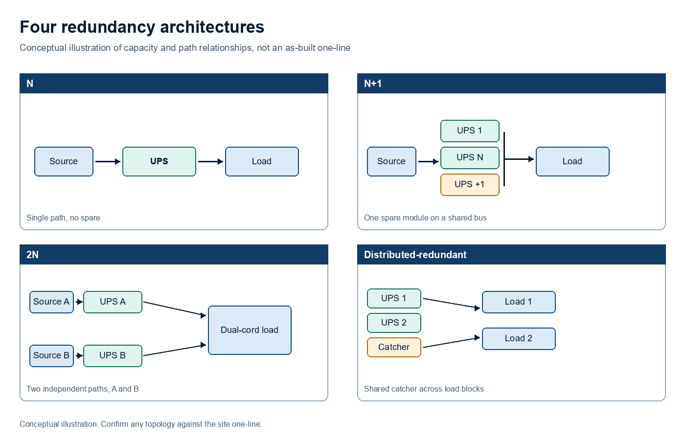
Conceptual illustration of four redundancy architectures. It shows capacity and path relationships only and is not an as-built electrical one-line for any site.
Static bypass and maintenance bypass are different paths
Static bypass and maintenance bypass are often described together, yet they serve different purposes and carry different risks. The static bypass is an automatic electronic path inside the UPS. When the inverter cannot or should not carry the load, the static switch transfers the load to the bypass source, normally raw unconditioned mains, within milliseconds. The load stays energized but loses conditioning, and the static path can become a common overload or fault path across parallel modules or frames. Eaton documents product-specific transfer and locked-bypass states for the Power Xpert 9395 family, so the installed manual and configuration govern the behaviour rather than a generic description. A static bypass does not isolate the UPS for service.
The maintenance bypass is a mechanical wrap-around path, built from breakers or a rotary mechanism, that routes the source around the UPS so the whole unit, including its static switch and often the battery, can be de-energized, isolated and physically removed while the load runs on utility. Make-before-break transfer keeps the load energized during the change. The exact as-built switchgear defines the transition type, the synchronization requirement, the breaker order, the interlocks, the neutral treatment, the energized boundaries and the restoration sequence. Schneider's Galaxy VX start-up from maintenance bypass procedure shows why a generic sequence is unsafe: it uses guided system steps, source and breaker confirmation, and backfeed protection specific to the product. A maintenance bypass can remove a complete UPS train from the protected path, so the remaining capacity during that state has to be calculated, not assumed.
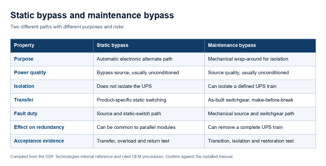
Bypass comparison drawn from our internal engineering reference and the cited manufacturer procedures. Confirm every value against the exact installed manual and one-line.
| Property | Static bypass | Maintenance bypass |
|---|---|---|
| Purpose | Automatic electronic alternate path | Mechanical wrap-around for isolation |
| Power quality | Bypass source, usually unconditioned | Source quality, usually unconditioned |
| Isolation | Does not isolate the UPS | Can isolate a defined UPS train |
| Transfer | Product-specific static switching | As-built switchgear, make-before-break |
| Fault duty | Source and static-switch path | Mechanical source and switchgear path |
| Effect on redundancy | Can be common to parallel modules | Can remove a complete UPS train |
| Acceptance evidence | Transfer, overload and return test | Transition, isolation and restoration test |
Comparing N, N+1, 2N and distributed-redundant
N means installed capacity equals the load on a single path with no spare, so any failure or planned service forces an outage or a drop to unconditioned bypass. It suits non-critical loads only. N+1 adds one unit beyond what the load needs, so a single failure, or a unit taken out for service, still leaves enough capacity, which makes it the common enterprise target. N+1 protects capacity, not the delivery path, so a single downstream bus or breaker can remain a common point of failure unless that path is duplicated as well.
2N provides two complete independent systems, each able to carry the whole load with separate paths from source to load. It removes the single points of failure that a shared path creates and lets a full path be worked on while the other carries load, at the highest capital cost and footprint. A bare 2N sizes each of the two paths to exactly N with no internal spare, so while one path is out for service the surviving path has no capacity margin for a component failure. A 2(N+1) arrangement makes each path itself N+1, which is why fault-tolerant objectives are generally built on 2(N+1) rather than a bare 2N.
Distributed-redundant designs share backup capacity across several load blocks rather than duplicating it per load. A common form places three systems in support of two loads, which delivers close to 2N-class resilience with fewer units and higher utilization, at the cost of more complex controls and tie arrangements. A related block-redundant form runs the primary systems at high load with a shared standby system, sometimes called a catcher, that picks up a failed block. Schneider Electric's design comparison warns that distributed arrangements have many operating states, can be difficult to balance, and depend on transfer equipment that may itself be a single point of failure.
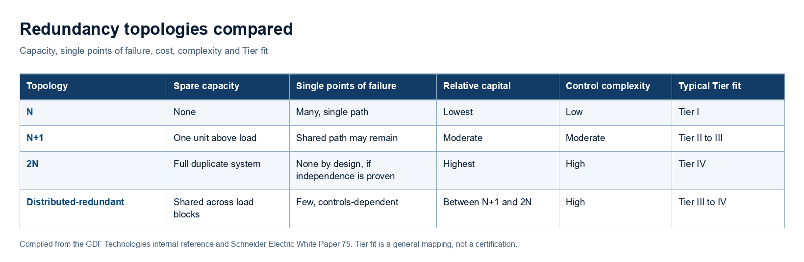
Topology decision matrix compiled from our internal engineering reference and Schneider Electric's UPS system design comparison. Tier fit is a general mapping, not a certification.
| Topology | Spare capacity | Single points of failure | Relative capital | Control complexity | Typical Tier fit |
|---|---|---|---|---|---|
| N | None | Many, single path | Lowest | Low | Tier I |
| N+1 | One unit above load | Shared path may remain | Moderate | Moderate | Tier II to III |
| 2N | Full duplicate system | None by design, if independence is proven | Highest | High | Tier IV |
| Distributed-redundant | Shared across load blocks | Few, controls-dependent | Between N+1 and 2N | High | Tier III to IV |
The comparison that matters is not which topology is strongest in the abstract but which one matches the availability requirement at an acceptable cost and complexity. A distributed-redundant design can reach 2N-class resilience with three systems instead of four across two blocks, which lowers capital and raises utilization, but it moves risk into the transfer equipment and the controls. A 2N design removes that dependency at a higher unit count. The owner sets the acceptable exposure; the engineering task is to make the exposure of each option explicit.
Mapping topology to Uptime Institute Tier objectives
The Uptime Institute classifies facility infrastructure in four tiers. Tier I is basic capacity on a single distribution path with no redundancy. Tier II adds redundant capacity components but keeps a single path. Tier III is concurrently maintainable, with a redundant delivery path so any component can be serviced without dropping the IT load, generally implemented as N+1. Tier IV is fault tolerant, with independent and physically separated systems, generally built on 2(N+1), so that a single equipment failure is stopped short of the IT load even while a distribution path is being maintained. A bare 2N meets the two-path requirement, but without an internal spare in each path it does not retain redundancy while one path is out, which is why fault tolerance generally calls for 2(N+1).
Concurrent maintainability and fault tolerance are different objectives. The Uptime Institute distinguishes a concurrently maintainable design, which can still be exposed to an equipment failure or an operator error during maintenance, from a fault-tolerant design, which adds protection against a failure while a path is out. A Tier III facility does not guarantee that every simultaneous failure is covered; the owner defines whether one path out plus a fault on the survivor is an accepted exposure.
Availability percentages require care. The Uptime Institute removed expected-downtime figures from its Tier standard in 2009 on the basis that operations, not topology alone, drive real availability. Figures still circulate in secondary industry sources, commonly cited as about 99.671 percent for Tier I, 99.741 percent for Tier II, 99.982 percent for Tier III and 99.995 percent for Tier IV, but these are planning heuristics from those secondary sources, not guarantees published by the Uptime Institute. Treat them as rough context for a conversation, and attach any availability target to the analyzed dependencies, the failure assumptions, the maintenance state and the test evidence for the actual facility.
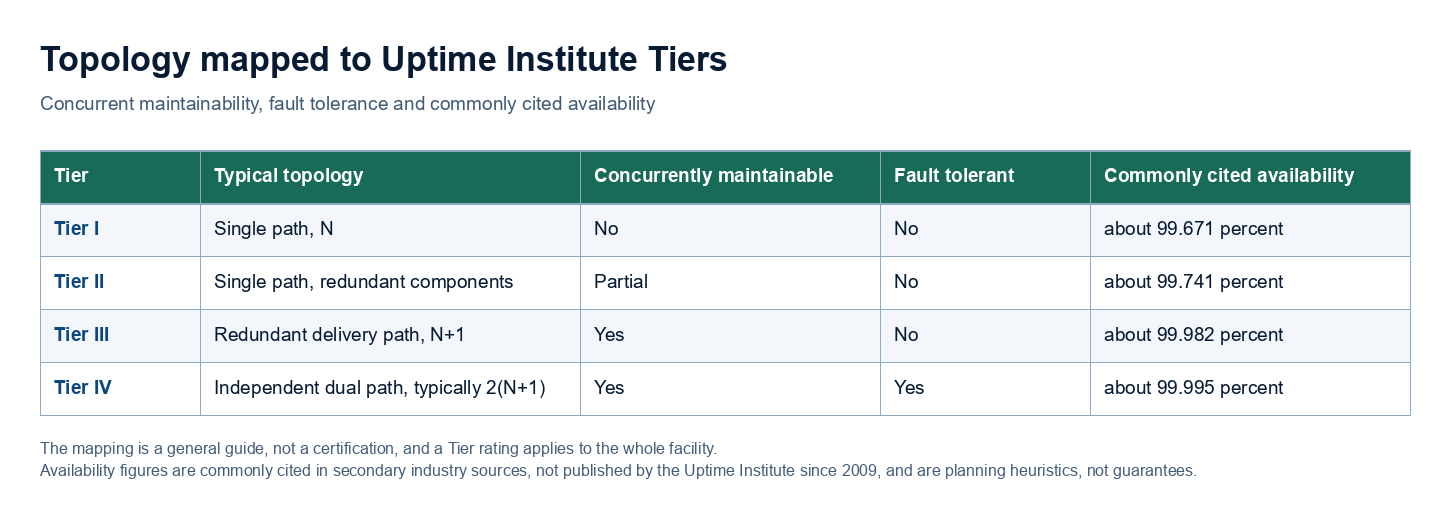
Tier mapping compiled from the Uptime Institute Tier classification material and secondary industry sources. The mapping is a general guide, not a certification, and a Tier rating applies to the whole facility. The availability figures are commonly cited in industry and have not been published by the Uptime Institute since 2009; they are planning heuristics, not guarantees.
| Tier | Typical topology | Concurrently maintainable | Fault tolerant | Commonly cited availability |
|---|---|---|---|---|
| Tier I | Single path, N | No | No | about 99.671 percent |
| Tier II | Single path, redundant components | Partial | No | about 99.741 percent |
| Tier III | Redundant delivery path, N+1 | Yes | No | about 99.982 percent |
| Tier IV | Independent dual path, typically 2(N+1) | Yes | Yes | about 99.995 percent |
The state-based method for proving a topology
Because a label can hide a shared dependency, redundancy is proven by state rather than by the one-line. The method defines N in a named state, removes one specified component or path, calculates the remaining qualified capacity, traces every shared source and dependency to each load input, and verifies that transition and recovery do not create an unacceptable exposure. It records what conditioning, isolation, redundancy and safety margin remain in each state.
The dependency trace is the step that most often changes a conclusion. Power-module redundancy does not prove energy-storage redundancy: a shared battery bus, shared DC protection, or a string whose remaining discharge power is inadequate at the post-failure load can leave a system short even when the module count looks correct. A shared cooling controller, a common fuel component, a single EPO or fire relay, a shared programmable controller, or a downstream panel that both cords depend on can each remove more paths than the redundancy claim allows. A shared element defeats independence whenever its failure, maintenance or operation removes more paths than the claim permits.
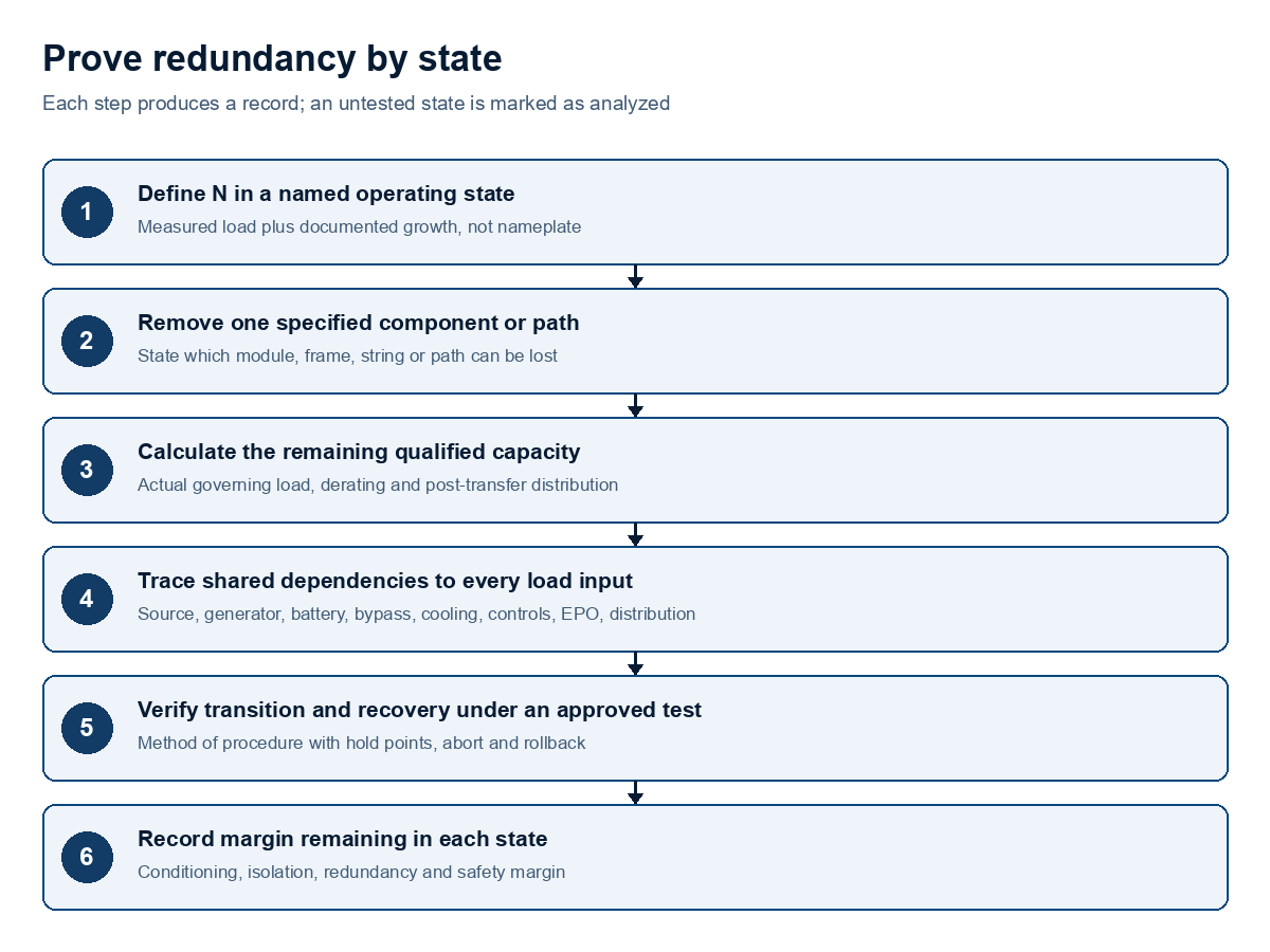
The state-based evaluation method from our internal engineering reference. Each step produces a record, and an untested state is marked as analyzed rather than witnessed.
Transitions can govern the result even when the steady state passes. Module isolation, frame isolation, source transfer, generator pickup, battery-string removal, static-bypass operation and maintenance-bypass evolution each create a state before, during and after the change that has to be calculated. A method of procedure establishes a verified hold point before the system crosses into a reduced-reserve state and another before it returns, and it does not assume that reversing the prior steps produces a valid restoration sequence.
Canadian facility realities and anonymized field patterns
On Canadian three-phase projects, three patterns recur in our field work. The first is that the redundancy basis has to be pinned before sizing. On a fleet asset evaluation involving two units in parallel, the engineering team paused before sizing to confirm whether the requested N+1 was calculated on the nominal capacity requested or on the actual measured load, because the answer changes the module count and the price. Two units in parallel are N+1 only relative to a defined N.
The second is that the maintenance bypass and the physical space, not the UPS, often decide feasibility. On a constrained federal-facility replacement, the binding constraint was the maintenance bypass: there was no wall location for a bypass panel and no floor space for an external bypass cabinet. The team confirmed that the UPS itself fit, a 79-inch unit in an 82-inch space, and then had to solve for a free-standing bypass without a three-month lead time that would have stalled the cutover. A unit that fits but cannot be maintained without dropping load does not meet the requirement, so the maintenance state is solved before the equipment is selected.
The third is that installed modules, not frame capacity, define redundancy. When a client questioned an 18 kW modular quotation, the team clarified that three installed 6 kW power modules produced the installed capacity, and that empty slots do not provide redundancy while the shared frame, bus, bypass and controls remain common. The installed-modules point applies whether a system sits above or below the 20 to 30 kW three-phase threshold. For any installed system, data-centre UPS maintenance and acceptance support begins with the exact model, the electrical one-line and the current operating state rather than a nameplate.
A Canadian efficiency consideration belongs with the topology choice. High-efficiency modes, such as Schneider Electric's eConversion (previously styled ECOnversion) or a comparable manufacturer eco-mode, can lift operating efficiency toward the high nineties, but they change how the load interacts with the static bypass and the inverter, so the source quality, the load tolerance, the transfer behaviour and the fault-clearing behaviour must be confirmed for the installed model and site before the mode is relied on in a redundant design.
Failure modes, limitations and safety boundaries
The failure modes that undermine a redundancy claim are consistent: an incorrect or stale N, unrecorded load growth, an unavailable spare module, uneven load sharing, a shared bus or bypass mistaken for independence, an unavailable or unsynchronized bypass source, a wrong breaker sequence, a defeated interlock, an out-of-date one-line, overlapping maintenance that removes reserve, an open battery string, non-independent STS sources, both load cords on one path, and a procedure copied from another model. Human error is treated as a system issue that involves procedures, labels, training, staffing and change control, not individual blame.
This paper provides technical guidance, not a sealed design, a commissioning certificate, an authority approval or a manufacturer approval. The comparisons rest on the cited manufacturer and standards sources and on anonymized field patterns from our own projects, and no availability figure here is presented as a guaranteed outcome. Safety boundaries apply to every state discussed: energized-work limits, lockout ownership, arc-flash and battery hazards, and the qualified-person boundary belong to the exact installation and its authority having jurisdiction, and a live critical load is never switched merely to prove a drawing. Testing requires an approved method of procedure with named roles, hold points, abort criteria and rollback.
Decision checklist before committing to a redundancy target
-
Define N on measured load, not on a nameplate or a nominal request. Record the critical load in kilowatts and kilovolt-amperes, the power factor, the phase balance, the peak and its duration, and documented growth, then state the operating condition in which N applies. Where interval metering is absent, take the load from UPS and PDU trend logs or a power-monitoring system rather than from the nameplate.
-
Choose the topology from the availability requirement. Select N+1, 2N or distributed-redundant against the facility's real resilience need and its acceptable cost and complexity, and record why the chosen exposure is acceptable to the owner.
-
State the layer at which redundancy is claimed. Separate module redundancy inside a frame from system redundancy between frames or trains, and confirm that the delivery path, not only the capacity, carries the required redundancy.
-
Trace every shared dependency to each load input. Include the source, generator, switchgear, battery, bypass, cooling, controls, EPO, fire interface and downstream distribution, and prove both dual-cord and single-cord behaviour.
-
Solve the maintenance bypass and physical access early. Confirm the bypass topology, rating, transition, energized boundaries, footprint and lead time before selecting the UPS, because the bypass is often the binding constraint.
-
Evaluate energy-storage redundancy separately from module redundancy. Confirm the string arrangement, DC isolation, remaining discharge power and runtime at the post-failure load, and the management and recharge behaviour after an outage.
-
Make commissioning evidence part of procurement. Require load-bank tests, transfer traces, battery discharge results, bypass and isolation tests and acceptance limits in the purchase specification, and compare UPS systems available in Canada only after the technical schedule is complete.
Records required before committing to a redundancy target
Before a Canadian owner commits to a redundancy topology, confirm the measured load and documented growth, the operating state in which N applies, the layer at which redundancy is claimed, the traced dependencies to every load input, the maintenance-bypass and access solution, the separate energy-storage analysis, and the commissioning evidence that will prove the target. A firm topology decision, design or procurement release should follow only after those records exist and the owner has accepted the residual exposure.
Sources
- Uptime Institute, Explaining the Uptime Institute's Tier Classification System
- Schneider Electric, Comparing UPS System Design Configurations, White Paper 75
- Schneider Electric, Cost, Speed, and Reliability Tradeoffs between N+1 UPS Configurations
- Eaton, Power Xpert 9395 UPS Installation and Operation Manual
- Schneider Electric, Galaxy VX Start-Up from Maintenance Bypass
- Encor Advisors, Data Center Tiers Explained
- Internal engineering library, UPS Redundancy, Bypass and Concurrent Maintainability
- Internal engineering library, Three-Phase and Data Center Power
- Internal engineering library, Field Case Library: Engineering and Quoting Patterns
Request a system quote
Tell us the application and we reply within 4 business hours with the sizing, the right system, the installation and a written quote. Three-phase installs usually need a licensed electrician, so let us know if you have one.
Brand names are trademarks of their owners and are used only to identify the equipment we service. We are not the manufacturer and are not affiliated with it.